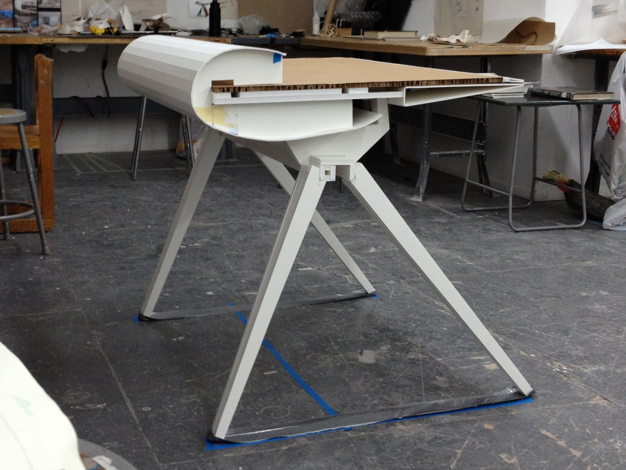
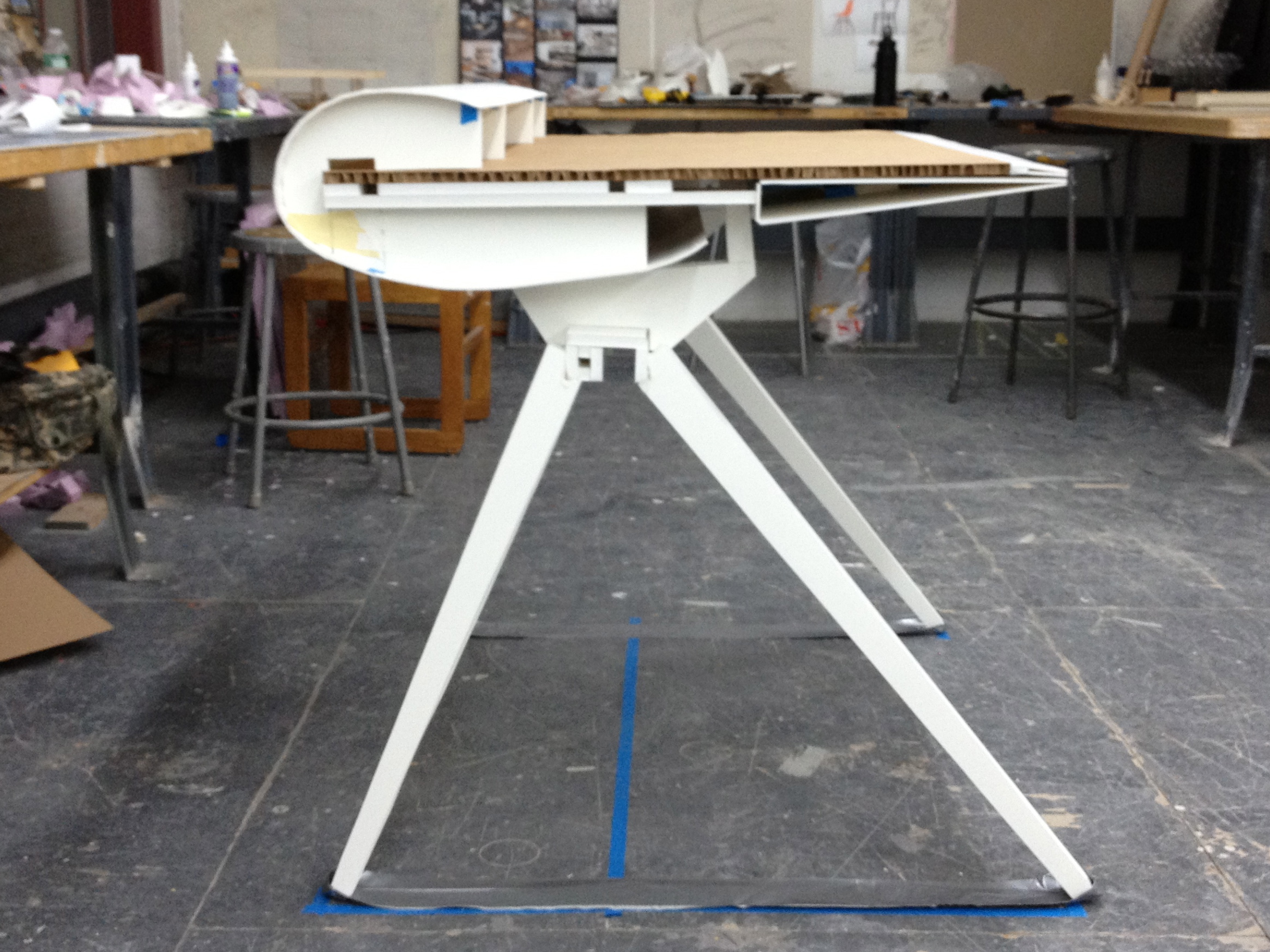
Next week is the concept presentation to the rest of the class. For me, I decided that the best way to convey my thoughts is a full-size model. Through discussions with Mark, I realized that I've been spending too much time designing the body of the table but not much the legs. Functionally, I know the legs must have a way to encapsulate cables if needed, but I have no idea how the body and the legs would come together. This full size model would be a way to help me think about it, especially since it will also help me think about the strength of materials that will be needed to support everything.
The concept for the installation of this desk is a three step process.
1. Construct the legs/support.
2. Install the wiring module.
3. Insert the table top.
Keeping that in mind, there could be a component that has a lot of strength that is at the core of this piece of furniture. the wiring module I made last week calls for a cantilevering table top, so it makes sense for me to incorporate this strong part where legs, wiring module and tabletop would come together.

Wouldn't it be wonderful if this could be an extruded aluminum piece? The next step would be to rise it to the right height, 30" from the ground to the top of the desk surface... so I constructed a temporary jig. Also, from now on this piece would be called the core module.

and now to mockup how it would look with the wiring module installed.

… Now I need to somehow encapsulate the core into the wiring harness… Unfortunately the design of the wiring harness has the table top flush against its side or wider so I had to cut apart the wiring harness.

This also means the legs would actually be really start really far back. That's ok if the legs were more in a "L" shape, pedestal like… a lot of torque on that core module and the table top. This might not be a good idea, so I restored the wiring module back to one piece. And moved the core module under the body of the table.

This gives me a bit more space for the wires. And now there could be some kind of trap door that opens from the back like the original design.

Now, for the legs… I know I definitely want the legs to cover as much foot print as the dimensions of the tabletop and wiring harness. This should provide enough leverage so the desk won't tip over easily… so I marked up the foot print on the floor with painter's tape.

I really wasn't thrilled with all the ideas I had previously for the legs of this table. Simple perpendicular legs seemed too plain for this table. Metal rod, Eames-desk like legs looked too '60s retro. Taking bent cues from airplane landing gears seemed too literal and overly complicated, though maybe appropriate if this table was literally made from a salvaged wing. Since the core is already out of the wire harness, perhaps an off-center saw horse might be ok. In the picture above, the horizontal blue line on the floor is not half way between the front and the back. It is just behind the center of mass of the table top and wiring module.
I also decided that the legs should lean in from the sides a little to provide a little more stability and look slightly more evolved than just a sawhorse… perhaps the legs should be tapered?


So how does it look with the rest of the table?

There really should be a space between the table and the core module. By the way, the duct tape on the floor is just a temporary strap brace I made to keep the legs from splitting apart should the model get too heavy.

Unfortunately there's a space below the table top where the spacer would support the table so it made this weird angle.

This reminds of the architect tables I use to work with. Looks interesting but really isn't something I want right now. Perhaps a feature to offer later? So now, with the temporary spacer installed, this is what the installation would look like.
1. Get the legs standing.

2. Install the wiring module.

3. Install the desk top.

Here is how it might look so far from different angles.
What have I learned? Well, right now...
• I still haven't figure out how to resolve the issue of the rounded 2nd tier that will stop the user from putting anything there.
• The legs are ok now, though I need to figure out how to route cables through it from the wiring module.
• The core module may be too low… user may hit it. Forgot to sit down at the table to see. Duh!
• The core module no longer has to be in that side profile shape… so there could be some more design there.
• The tapering of the front lip of the table to give a more comfortable angle for the user's arms is a good idea but maybe not so apparent?
• The "style" of the spacer is still a little undecided. There is opportunity for design there.
• The way the legs are now, really gives users much more space to approach the cables from the back of the table but perhaps not so much from the lower front. Again, need to craw up to the table to see.
• With the removal of the core module from the wiring module means there is much more space in there now for cable-caching, which means I can start designing how the interior of this table should be laid out.


